QCORE Seminar Series · October 29, 2025
Featuring Trent Jackson
📄 Access the full slide deck
Why We Hosted This Talk
QCORE’s hybrid quantum/classical network work has already demonstrated something exciting: quantum key distribution can coexist alongside classical communications in real-world fiber networks. But the next step is making those systems more deployable, reconfigurable, and scalable—and that’s where free space optical (FSO) links become compelling.
In this seminar, Trent Jackson walked through the practical engineering realities of building airborne FSO links, especially in the context of a campus-wide network that could extend quantum and classical connectivity into the air. The talk covered the full chain—from pointing and atmospheric effects to platform limits and prototype hardware—framed by a simple question: “You point a couple lasers at each other and it works… right?”
About the Speaker

Trent Jackson
Trent Jackson is a Senior Research Engineer at Spectrum Lab, working on airborne and optical platform concepts, including free space optical transceivers, pointing/acquisition/tracking (PAT) systems, and system integration challenges that show up when optical links leave the benchtop and enter real environments.
A Blast from the Past: The First FSO Link Was Built in 1880
Trent opens by pulling the audience into the past—back to 1880, when Alexander Graham Bell demonstrated what is widely credited as the first free space optical link using the “Photophone.” Sunlight was modulated by a vibrating mirror diaphragm, transmitted building-to-building, detected with selenium, and converted back into sound. Bell reportedly called it the greatest invention he ever made, even better than the telephone.
The reason for starting here isn’t nostalgia—it’s perspective. If a working optical link was possible with 19th-century tools and sunlight, what makes modern airborne laser links feel so hard in practice? That tension is basically the theme of the talk.
Why Free Space Optics, When RF Already Exists?
FSO is not “laser for the sake of laser.” In this project’s context, the motivation is deployment: moving from a fiber-bound demonstration to something that can become campus-scale, reconfigurable, and airborne.
Trent frames airborne platforms (drones, autonomous UAVs, aerostats) as an enabling layer—especially as their cost has dropped and usability has improved. The same approach that supports quantum/classical networking also opens classical use cases: non-line-of-sight communications, wireless connectivity extensions, and disaster relief scenarios. (Slide 3, Slide 4)
He also points out that FSO isn’t only about communications. It can support rapidly deployable sensing networks, where distributed nodes collect RF information and upconvert it onto optical links. With multiple nodes, techniques like time difference of arrival can help geolocate emissions.
The Core Reality Check: What’s Actually Hard About Airborne FSO?
Once the link moves into the air, you’re not just dealing with optics. You’re dealing with a system that has to survive platform motion, air effects, vibrations, and control-loop realities.
Trent organizes the hard parts into a practical set of constraints: pointing, acquisition and tracking (PAT), turbulence, platform vibration, payload power/weight limits, and how all of this interacts with coherent optical coupling—especially when you’re coupling into single-mode fiber.
Pointing Accuracy: The “Three Inches at a Kilometer” Problem
To make the project compatible with quantum sources, the system stays anchored in fiber optics. At 1550 nm, single-mode fiber has a mode field diameter around 10.5 microns. If you run a quick tolerance exercise—accepting roughly half power coupling loss—the allowed angular error becomes extremely small.
Trent converts that into a human-intuitive picture: at 1000 meters, the effective “target” you need to hold is under three inches in diameter. It’s not a metaphor; it’s what the optics demand.
Geometric Loss: Beam Divergence Adds Up Fast
Even with perfect pointing, divergence creates geometric loss because the beam spreads and gets clipped by the receive aperture at range.
Trent uses a concrete example: with a 1-inch beam diameter, 1-inch receive aperture, 1550 nm, and a 1 km link, the loss is about 8 dB, meaning roughly 83% of the light is gone from truncation alone. That kind of link budget reality has to be designed around, not discovered later.
Turbulence: The Atmosphere Is Not a Passive Medium
Turbulence becomes a second system layered on top of the optics. Trent highlights key quantities engineers track when trying to predict or manage atmospheric effects, including:
- Fried parameter (r₀): the atmosphere’s coherence diameter
- Greenwood frequency (fG): an estimate of turbulence bandwidth
- Rytov variance (σR²): related to scintillation (intensity fluctuations)
- Strehl ratio: how far the wavefront is from diffraction-limited performance, which matters directly for fiber coupling
The important point: turbulence doesn’t just steer beams off-target; it can distort the wavefront in ways that reduce coupling efficiency, even if the beam lands “in the right place.” (Slide 11)
Correction Strategies: Tip/Tilt vs Adaptive Optics (and Why Cost Matters)
There are two big correction classes:
- Tip/tilt correction uses a fast steering mirror that moves the beam back where it needs to go based on a detector (camera or quadrant detector). It’s relatively straightforward.
- Adaptive optics goes further: wavefront sensor + deformable mirror + high-end control loop, correcting higher-order distortions in the wavefront.
Trent’s framing is pragmatic: adaptive optics may be ~10× more expensive and ~10× more complex, so the project goal is to avoid needing it. That puts real constraints on link distance and turbulence tolerance. (Slide 12)
A useful rule-of-thumb shows up in the ratio of beam diameter D to Fried parameter r₀:
- When D ≪ r₀, wavefronts are near-flat; tip/tilt is usually sufficient
- Near D ≈ r₀, tip/tilt may still work but low-order aberrations creep in
- When D ≫ r₀, higher-order aberrations dominate and adaptive optics becomes unavoidable
That ratio becomes a practical “go/no-go” marker for how far you can scale with simpler correction strategies.
Drone Reality: Prop Wash, Vibrations, and Platform Motion
Airborne platforms introduce their own problems beyond the atmosphere.
Prop wash creates local turbulence slabs. One practical mitigation: adjust pointing geometry so the link shoots between rotors, not through disturbed air beneath them.
Vibrations matter too. Measurements on one platform showed dominant vibration frequencies around 60–90 Hz, which is high—but not hopeless. Trent notes that this is within the range that a fast steering mirror can correct for in a control loop. (
Then there’s platform motion: two drones can drift far enough that a fine steering mirror can’t compensate anymore. That leads directly into PAT design.
PAT Routines: How Two Moving Platforms Actually Find and Hold a Link
Trent lays out a typical PAT routine in stages:
First comes open-loop pointing, using GPS/INS and platform attitude to coarse-point gimbals. If the beacon isn’t acquired, the system transitions into a search pattern (spiral or raster) to find it.
Once acquired, the system enables closed-loop fine tracking, often with PID control (and optionally predictive feed-forward). Finally, there’s link maintenance and reacquisition—monitoring the link state and restarting acquisition if it drops.
Prototype Design: Hardware Choices Under Real Constraints
Trent then walks through the team’s prototype decisions, guided by constraints that came from the quantum source and from platform reality.
Because the entangled photon source operates in the C-band, the signal stays at 1550 nm. Course pointing error (about ±1° from the gimbal) required a fast steering mirror with enough angular range to cover that error. Weight limits varied by platform from roughly 5–20 kg. (Slide 19)
From there, the team chose:
- A beacon wavelength at 808 nm, because it’s low-cost, high-power, and easy to filter away from the signal channel
- A reflective focusing element: an off-axis paraboloid, with a central hole to send the beacon through
- A 1-inch beam diameter as a good starting point for early ranges (100 m to ~1 km)
In the optical layout, the signal and beacon share optics and then separate at a dichroic. The beacon goes to a detector used by the control loop to steer the mirror.
Control Loops and Detection: Quadrant Detectors vs Cameras
On the control side, the system reads beacon position (x/y) and drives the fast steering mirror through PID control. Trent shows how quadrant detectors produce differential signals and how those get digitized and turned into control output for the mirror driver.
He also highlights an active trade study: quadrant detectors are fast and simple, while cameras allow higher dynamic range, image processing, tolerance for non-uniform beams, and potentially wider field of view. The right choice depends on acquisition needs and operating conditions.
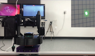
Early Results: Entanglement Through a 13-Meter Free Space Link
The team has already demonstrated quantum entanglement through a free space optical path around 13 meters, using these transceivers.
Trent cites reported performance including ~600 coincidence counts/sec and an S-parameter measurement of ~2.5—a strong early result, with clear intent to improve efficiency and performance as the design matures.
Testbeds, Tools, and “Making Pointing Easier Than Physics Wants It To Be”
Trent shows a gimbal testbed used for PAT development and mentions ongoing in-house gimbal design work aimed at improving accuracy and speed. (Slide 22)
He also highlights several parallel efforts aimed at improving coupling and system behavior:
- Fiber tip structures (nano-printed cones/lenses) that may expand or collimate the fiber mode and improve coupling tolerance (Slide 24)
- An aberration measurement and correction system, built after early prototyping revealed that some telescope designs introduce aberrations that degrade performance at longer ranges. The goal is to measure aberration, compare telescope designs, and potentially correct with printed optics on fiber tips. (Slide 25)
Platforms: Drones and Aerostats (and Why Tethering Helps)
Finally, Trent reviews the platforms being used and evaluated:
- A smaller aerial platform with ~5 kg payload and ~40 min endurance
- A larger drone platform capable of 30 kg payload and ~30 min endurance
- A tethered aerostat (“Sky Sentry”) lifting ~22 kg, with fiber optic cables in the tether, and endurance measured in days to a week+
The tethered aerostat adds a practical systems advantage: in some configurations, you can keep sensitive or heavy components on the ground and send optical signals up to the airborne node via fiber through the tether. (Slide 26)
Next Steps
The near-term roadmap is straightforward and engineering-driven: package prototypes into flight-ready enclosures, merge and test gimbal + fast steering mirror control loops, take the system outdoors for ground-based demonstrations, move into ground-to-air, then air-to-air testing, and incorporate airborne nodes back into the hybrid quantum/classical network architecture.
Q&A Highlights
Q1 —Why pick 808 nm for the beacon?
A: A major reason is practicality: it’s inexpensive, high power is readily available, and you can deliberately increase divergence to ease tracking while staying under eye safety limits.
Q2 — How sensitive is turbulence to environment and time of day?
A: Very. Trent notes turbulence parameters can change by orders of magnitude based on day/night transitions, elevation, temperature gradients between ground and air, and weather. That variability becomes a central challenge for robust real-world links.
Q3 — What’s the benefit of tethering an aerostat?
A: It enables configurations where parts of the system (including potentially a source) can remain on the ground and be delivered optically to the airborne node, reducing airborne payload complexity while still achieving airborne connectivity.
Q4 — Could you build relays or multi-hop airborne links?
Yes—Trent describes future modalities including relay concepts using multiple transceivers or reflective elements to route signals between multiple airborne nodes.
Q4 — What if GPS is compromised—how do you point and navigate?
Trent notes there isn’t a single replacement; alternatives may involve combinations of RF, LiDAR, cameras, and other sensing approaches, depending on the scenario.
| Ask Trent Have a question about airborne FSO links, turbulence limits, pointing/acquisition/tracking systems, or how hybrid quantum/classical networks could move into the air?Send it to QCORE—Trent may answer it in an upcoming feature. ➜ Submit a question |